
Key points and common problems in mold design
Release time:
2025-07-09
When starting the design, the parting direction and parting line must first be determined to minimize the need for ejector pins and sliders and to eliminate the impact of the parting line on the appearance.
I. Mold Opening Direction and Parting Line
When starting the design, the mold opening direction and parting line must first be determined to minimize the need for core-pulling slider mechanisms and eliminate the impact of the parting line on the appearance.
1. After the mold opening direction is determined, the product's reinforcing ribs, buckles, protrusions, and other structures should be designed to be as consistent as possible with the mold opening direction to avoid core pulling, reduce seam lines, and extend mold life;
2. After the mold opening direction is determined, an appropriate parting line can be selected to avoid undercuts in the mold opening direction, thereby improving appearance and performance.
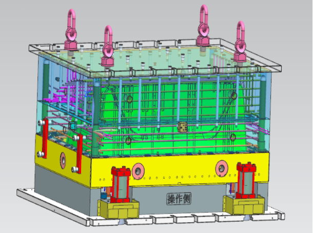
Figure 1 -- Huacheng Molding Case
II. Demolding Draft Angle
1. An appropriate demolding draft angle can avoid problems such as product fuzzing, topping damage (topping white/deformation/breakage), etc. The demolding draft angle for smooth surfaces should be ≥0.5 degrees, for fine textured (sandblasted) surfaces >1 degree, and for coarse textured surfaces >1.5 degrees.
2. When designing deep cavity products, the draft angle of the outer surface should be greater than that of the inner surface to ensure that the mold core does not deviate, resulting in uniform product wall thickness and ensuring the material strength of the product opening.
III. Product Wall Thickness
1. All materials have a certain wall thickness range, generally 0.5~4mm. When the wall thickness exceeds 4mm, it will cause excessive cooling time and problems such as shrinkage marks. Consider changing the product structure.
2. Uneven wall thickness will cause surface shrinkage, pores, and weld lines.
IV. Reinforcing Ribs
The reasonable application of reinforcing ribs can increase product rigidity and reduce deformation; the thickness of the reinforcing ribs must be ≤ (0.5~0.7) T product wall thickness, otherwise it will cause surface shrinkage; the single-sided draft angle of the reinforcing ribs should be >1.5° to avoid topping damage.
V. Fillet Radius
1. Too small a fillet radius may cause stress concentration in the product/mold cavity, leading to cracking of the product/mold cavity.
2. Setting a reasonable fillet radius not only avoids stress concentration problems but also improves the mold processing technology. For example, the cavity can be directly machined with an R-cutter, avoiding inefficient EDM.
3. Different fillet radii may cause the parting line to move. Different fillet radii or chamfers should be selected according to the actual situation.
VI. Hole Design
1. The shape of the hole should be as simple as possible, generally circular, with the axial direction consistent with the mold opening direction, to avoid core pulling.
2. When the length-diameter ratio of the hole is >2, a demolding draft angle should be set. In this case, the diameter of the hole should be calculated according to the minimum diameter (maximum material size). Generally, the length-diameter ratio of a blind hole is <4, which can prevent the punch needle from bending. Generally, the distance between the hole and the edge of the product is > hole diameter.
VII. Core Pulling and Slider Mechanisms
1. When designing products, core-pulling structures should be avoided as much as possible unless there are special requirements. If the axial direction of the hole and the direction of the rib are changed to the mold opening direction, methods such as cavity core piercing can be used.
2. When it is not possible to demold smoothly in the mold opening direction, a core-pulling slider mechanism should be designed. The core-pulling slider mechanism can form complex product structures, but it is prone to product seam lines, shrinkage, and other defects, and increases the mold cost and shortens the mold life.
VIII. Integral Hinge
1. Using the toughness of PP material, the hinge can be designed as an integral part of the product.
2. The size of the film used as the hinge should be <0.5mm and remain uniform,
3. With an integral hinge, the gate can only be designed on one side of the hinge.
IX. Inserts
1. Embedding inserts in the product can increase local strength, hardness, dimensional accuracy, and set small threaded holes (shafts) to meet various special needs. At the same time, it will increase the product cost.
2. Inserts are generally copper, but can also be other metals or plastic parts.
3. The part of the insert embedded in the plastic should be designed with anti-rotation and anti-pull-out structures, such as: knurling, holes, bending, flattening, shoulders, etc.
4. The plastic around the insert should be appropriately thickened to prevent stress cracking of the plastic part.
5. When designing inserts, the positioning method in the mold (holes, pins, magnetic) should be fully considered.
X. Markings
Product markings are generally placed on a relatively flat surface on the inner surface of the product and are raised. Choosing a surface where the normal direction is consistent with the mold opening direction, markings can be set to avoid scratches.
XI. Precision
Due to the unevenness and uncertainty of shrinkage rate, the precision of plastic parts is significantly lower than that of metal parts. The dimensional tolerances of mechanical parts cannot be simply applied. Appropriate tolerance requirements should be selected according to the standard. Designers can determine the dimensional tolerances of the workpiece according to the standard regulations and use appropriate calculation and design methods to ensure mold precision. At the same time, the design tolerance precision should be determined based on the comprehensive strength of the factory and the design precision of similar products.
XII. Deformation
Improve the rigidity of the product structure and reduce deformation. Avoid flat structures as much as possible, reasonably set flanges, and concave-convex structures. Set reasonable reinforcing ribs.
XIII. Fasteners
1. Design the fastener device so that multiple fasteners are used simultaneously, so that the entire device will not fail to operate due to damage to individual fasteners, thereby increasing its service life. Also, consider adding fillet radii to increase strength.
2. The tolerance requirements for the relevant dimensions of the fasteners are very strict. Too many undercut positions are easy to cause fastener damage; conversely, too few undercut positions make it difficult to control the assembly position or the combined parts are too loose. The solution is to reserve a method for easy mold modification and adding glue.
XIV. Welding (Hot Plate Welding, Ultrasonic Welding, Vibration Welding)
1. Using welding can improve the connection strength.
2. Welding can simplify product design.
Fifteen. Reasonably consider the contradictions between process and product performance.
1. When designing a product, the contradictions between product appearance, performance, and process must be considered comprehensively. Sometimes sacrificing some processability can result in good appearance or performance.
2. When structural design cannot avoid defects, try to make the defects occur in hidden parts of the product.
Sixteen. Relationship between the screw pillar hole diameter and the self-tapping screw diameter
Self-tapping screw - screw pillar hole diameter
M2--1.7mm、M2.3--2.0mm、M2.6--2.2mm、M3--2.5mm
Seventeen. Design principles of BOSS
1. Pillars should not be used alone; they should be connected to the outer wall or used with reinforcing ribs to strengthen the pillar and make the material flow more smoothly.
2. The height of the pillar is generally not more than two and a half times the diameter of the pillar. Because a pillar that is too high will cause air trapping when the plastic part is molded (too long will cause air holes, burning, insufficient filling, etc.).
3. If the pillar height exceeds two and a half times the diameter of the pillar, especially for pillars far from the outer wall, the way to strengthen the pillar is to use reinforcing ribs.
4. The shape of the BOSS is mainly circular; other shapes are difficult to process.
5. The position of the BOSS should not be too close to the corner or the outer wall; it should maintain a certain distance from the outer wall of the product.
6. The surrounding area of the BOSS can be partially thinned (i.e., opening a crater) to prevent shrinkage and subsidence.
7. Demolding angle of BOSS: Usually 0.5° for external and 0.5° or 1° for internal.
Eighteen. Several principles for selecting parting lines:
1. Ensure that the product can be removed from the mold; the parting line should be selected at the position of the largest projection edge shadow in the product demolding direction.
2. For appearance parts, mold parting cannot affect the appearance; appearance quality and precision must be ensured.
3. Ensure that the product remains in the back mold after opening the mold, which is conducive to demolding and side core pulling.
4. Ensure the quality of the product and the strength and rigidity of the parts during molding.
5. Consider the clamping force of the mold and place the direction with the large product projection area in the closing direction of the front and rear molds.
Nineteen. Explanation of several mold terms appearing in this article
1. Undercut refers to the part on the mold that obstructs the demolding of the product, preventing the product from being removed smoothly.
2. Parting line is the line formed on the product where several parts forming the mold cavity are joined together.
3. Parting surface is the contact surface between several parts forming the mold cavity.
4. The contact surface between the product and the mold on the mold is collectively called the gate surface.
5. Demolding is the action of smoothly removing the product from the mold.
6. Demolding direction is the direction that allows the product to be smoothly removed from the mold.
7. Appearance surface is the outer surface of the product, the surface that can be directly seen after assembly.
8. Clamping force is the force exerted by the injection molding machine on the mold to counteract the injection pressure.
Twenty. Common problems in mold design
1. Mold structural design: Mold structural design is a basic link in mold design. Reasonable mold structure can improve production efficiency and product quality. Common mold structural problems include excessive mold size deviation, overly complex part structure, and unreasonable selection of mold materials.
2. Mold material selection: The selection of mold materials directly affects the quality and service life of the mold. Common mold materials include steel, aluminum alloy, and plastic. When selecting materials, factors such as the mold's working environment, working temperature, and service life need to be considered.
3. Mold processing technology: Mold processing technology has an important impact on the quality and precision of the mold. Common problems in mold processing technology include unreasonable process routes, inaccurate process parameter settings, and substandard processing accuracy.
4. Mold maintenance and maintenance: Mold maintenance and maintenance are important links in ensuring the service life of the mold. Regular maintenance and maintenance of the mold, including cleaning the mold, lubricating the mold, and replacing worn parts, can extend the service life of the mold.
Disclaimer : Only for the exchange and sharing of composite material professional knowledge and market information, not for any commercial purposes. If there are any copyright issues or questions about the content, please contact us immediately. We will deal with it in time.
Related News

Huacheng mold to become a professional manufacturer of composite mold industry
Contact Us
Contact: Fan Qionglin 86-18858635168
E-mail:fql@hc-mould.com
Address: Chatang Village, Baihe Town, Tiantai County, Taizhou City, Zhejiang Province
Online message